Company Details

Shandong Xindadi Holding Group Co., Ltd
Company Details
Shandong Xindadi Holding Group Co., Ltd


 May 13, 2022
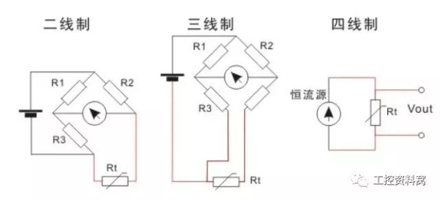
The two-wire, three-wire, and four-wire systems we reviewed refer to various transmitters whose outputs are imitating DC current signals, and the differences in their operating principles and layouts do not only refer to the wiring method of the transmitter. Otherwise, the thermocouple with millivoltmeter to measure temperature can be called the pioneer of the two-wire system!
Let's take a look at their definitions first.
Two-wire system: The two wires and the transmission power supply transmit signals, that is, the load and power supply output by the sensor are connected in series, and the power supply is introduced from the outside, and is connected in series with the load to drive the load.
Three-wire system: The three-wire sensor means that the positive terminal of the power supply and the positive terminal of the signal output are separated, but they share the same COM terminal.
Four-wire system: two wires for power and two wires for signal. Power and signal work separately.

The name of the several-wire system only came into being after the birth of the two-wire transmitter. This is the result of the extensive use of electronic amplifiers in appearance. The essence of expansion is an energy conversion process, which is inseparable from power supply. Therefore, the first presented is a four-wire transmitter; that is, two wires serve as the power supply, and the other two wires serve as the output transformed and expanded signals (such as voltage, current, etc.). The appearance of the combined appearance of the DDZ-Ⅱ electric unit. The four-wire transmitter with a power supply of 220V.AC and an output signal of 0-10mA.DC has been widely used. At present, it can be seen in some factories.

In the 1970s, China began to produce DDZ-Ⅲ electric unit combination appearance, and selected the World Electrotechnical Commission (IEC): Process control system with imitation signal specification. That is to say, 4-20mA.DC is selected for the external transmission signal, and 1-5V.DC for the contact signal, that is, a signal system with current transmission and voltage acceptance is selected.
Choose 4-20mA.DC signal, the appearance of the scene can complete the two-wire system. However, due to conditions, the two-wire system was only selected for pressure and differential pressure transmitters, and the four-wire system was still used for temperature transmitters. Nowadays, the product scale of domestic two-wire transmitters has also been greatly expanded, and the application fields have also increased. Most of the transmitters that come in from abroad are also two-wire systems.
Difference search for different wire transmitters
One or two wire system
Because to complete the two-wire transmitter, it is necessary to satisfy the following conditions together:
1. V≤Emin-ImaxRLmax
The output voltage V of the transmitter is equal to the regular minimum power supply voltage minus the voltage drop of the current on the load resistance and the transmission wire resistance.
2.I≤Imin
The normal operating current I of the transmitter must be less than or equal to the output current of the transmitter.
3. P<Imin(Emin-IminRLmax)
The minimum power consumption P of the transmitter cannot exceed the above formula, generally <90mW.
In the formula: Emin = minimum power supply voltage, for most appearances Emin = 24 (1-5%) = 22.8V, 5% is the negative change allowed by the 24V power supply;
Imax=20mA;
Imin=4mA;
RLmax=250Ω+transmission wire resistance.
If the transmitter satisfies the above three conditions in the planning, the two-wire transmission can be completed. The so-called two-wire system means that the power supply and the load are connected in series and have a common point. However, the signal communication and power supply between the field transmitter and the control outdoor meter only use two wires, which are both power wires and signal wires. Because the signal starting current is 4mA.DC, the two-wire transmitter provides static operating current for the transmitter. At the same time, the external electrical zero point is 4mA.DC, which does not coincide with the mechanical zero point. This "live zero point" is conducive to identifying breaks. Problems such as electricity and disconnection. In addition, the two-wire system also facilitates the use of safety barriers, which is conducive to safe explosion protection.

The two-wire transmitter is shown in Figure 1. Its power supply is 24V.DC, the output signal is 4-20mA.DC, the load resistance is 250Ω, and the negative wire potential of the 24V power supply is the lowest. It is the signal common line. The transmitter can also load the FSK keying signal of the HART protocol on the 4-20mA.DC signal.

Two, four-wire system
Because the 4-20mA.DC (1-5V.DC) signal system is widespread and used, in order to facilitate the connection in the use of the control system, the signal system is required to be consistent. For this reason, some non-electric unit combinations are required, such as online analysis. The output of 4-20mA.DC signal system can be selected for the appearance of, mechanical quantity, power, etc., but because of the messy conversion circuit and high power consumption, it is difficult to satisfy all the above three conditions, and it is impossible to achieve a two-wire system. You can only use an external power supply as a four-wire transmitter with an output of 4-20mA.DC.
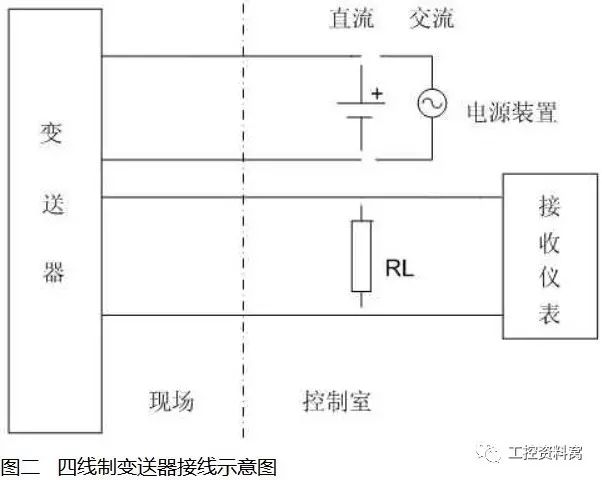
The four-wire transmitter is shown in Figure 2. Most of its power supply is 220V.AC, and some power supply is 24V.DC. The output signal is 4-20mA.DC, the load resistance is 250Ω, maybe 0-10mA.DC, the load resistance is 0-1.5KΩ; some also have mA and mV signals, but the load resistance or input resistance is not due to the output circuit method. Same but different values.

Three, three-wire system
In order to reduce the volume and weight of the transmitter, improve the anti-interference function, and reduce the wiring, some exterior manufacturers changed the power supply of the transmitter from 220V.AC to low-voltage DC power supply, such as the power supply from 24V.DC power box Access, because the low-voltage power supply invented conditions for negative wire sharing, so there are three-wire transmitter products.
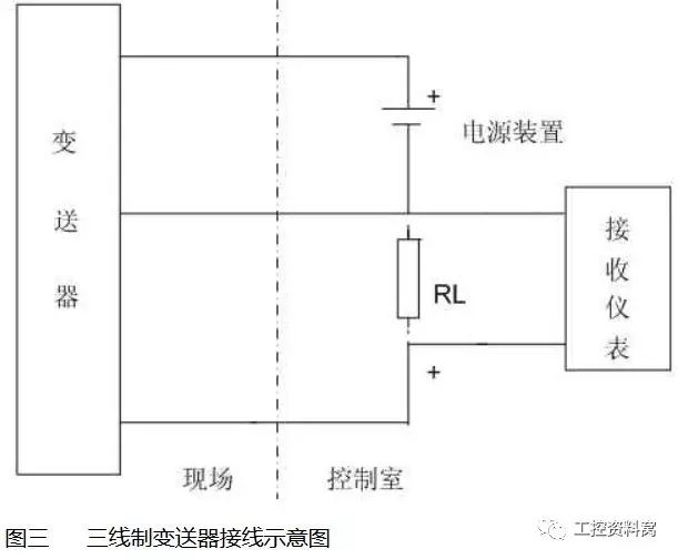
The three-wire transmitter is shown in Figure 3. The so-called three-wire system means one wire is used for the positive terminal of the power supply, one wire is used for the positive terminal of the signal output, and the negative terminal of the power supply and the negative terminal of the signal share one wire. The power supply is mostly 24V.DC, the output signal is 4-20mA.DC, the load resistance is 250Ω or 0-10mA.DC, the load resistance is 0-1.5KΩ; some also have mA and mV signals, but the load resistance or input Resistance, the value is different due to the different output circuit mode.
In the above three figures, the input and external appearance is the current signal. If the resistor RL is connected in parallel, the voltage signal is accepted.
It can be seen from the above description that because the operating principles and layouts of various transmitters are different, and then different products are presented, the two-wire, three-wire, and four-wire wiring methods of the transmitter are determined. Regarding the user, the selection should be based on the actual situation of the unit, such as the consistency of the signal system, the requirements for explosion protection, the requirements for receiving equipment, and the investment.
It should be pointed out that the 4-20mA.DC signal output by the three-wire and four-wire transmitters, because the principle and layout of the output circuit are different from those of the two-wire system, so whether the output negative terminal is compatible with The negative line of the 24V power supply is connected? Is it possible to share the ground? This is to be noted. If necessary, blocking methods can be adopted, such as using an isolator, safety barrier, etc., in order to share power with other external surfaces, share the ground and prevent additional interference from occurring .

 Two-wire system and four-wire system mutual change search
It can be seen from the above that all kinds of wire transmitters can exist, there is always a reason for existence, otherwise there will not be so many wire systems, it is very difficult for the user to change the wire system, and it is also of practical significance. Not big.
If you want to change the four-wire transmitter with a transmission signal of 0-10mA.DC to a two-wire system, the first problem encountered is that its initial current is zero. When the current is zero, the transmitter’s electronic The amplifier cannot establish a working point, so it will be difficult to work normally. If the DC power supply is used and the original constant current characteristics of the instrument are guaranteed, when the load resistance of the transmitter is 0-1.5KΩ, the feedback moving coil resistance in series with it is about 2KΩ. When the output is 10mA, the voltage drop of these two parts When it is greater than 24V, that is to say, 24V.DC is used for power supply, and the load is 0-1.5KΩ, it is impossible to ensure the constant current characteristics, and it is not possible to talk about using two-wire transmission.
In the 1970s, there was an instrument factory that changed the 0-10mA.DC four-wire transmitter to a two-wire transmitter. The specific method was to improve the original transmitter circuit and change the power supply voltage. It is increased to 48V.DC, but the initial current of the transmitter still cannot be zero. For this reason, a negative current is used to offset the initial output current of 4mA on the load resistance. However, such products have not been promoted and applied.
If you want to change the two-wire system to the four-wire system, there is no need at all. Moreover, this is a technical retrogression.
The above is the Definitions of two-wire, three-wire, and four-wire system we have listed for you. You can submit the following form to obtain more industry information we provide for you.
You can visit our website or contact us, and we will provide the latest consultation and solutions
Send Inquiry
Most Popular
lastest New
Send Inquiry


